 |
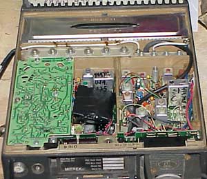
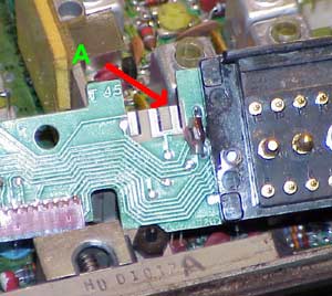
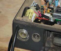
This photo shows the location of the PL
board on the left.
There are three types of PL boards for the Mitrek that I know of. There is the reed type, the 'code plug' (synthesized PL) type and a board that creates DPL (digital PL) via a 'code plug'. Creating your own 'code plug', allowing you to select any PL you desire is not hard and just involves a handful of 100k resistors soldered into the proper places. Information on how to do this is online (and I'll add a link later).
|
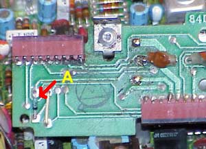 |
One of the things that I find disappointing
with the Mitrek PL boards is that they cannot chew gum and spit at the
same time. What?
The Mitrek PL boards cannot decode PL tones while they are encoding them. If you wish to use the Mitrek PL board for encoding, your life is easy-- as when the repeater goes into transmit, your PL board will also and encode a fine tone. For those like me, who wish to use the Mitrek PL board for decoding, you must remove a diode and cut a trace in order to keep the board from noticing that the transmitter is active. The yellow 'A' to the left shows the diode on the back of the 'interconnect board' which I cut out as one of the two mods to the PL system. The other mod is to break the trace between pin-4 of the PL plug and R38 (47k), which will keep the PL board in receive mode. Analog PL boards only. |
 |
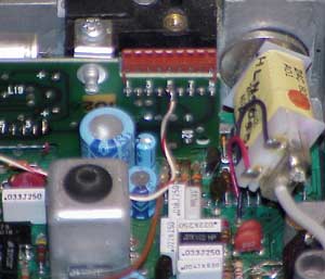
By the way, while I have the
interconnect board open, the green 'A' points to the spot where a little
jumper is placed between the two sides of the board to enable the
'extender' (noise blanker) often found in the better low-band Mitreks.
There are three positions for removable jumpers here, I've never looked into what the other two are used for.
|
 |
This view shows the PL board connection
to the interconnect board and my little wire tacked on to the pin-5
output of the PL decoder.
At Pin-5 you should find that it goes HI (near 12v) when the PL is properly decoded.
|
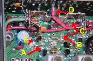 |
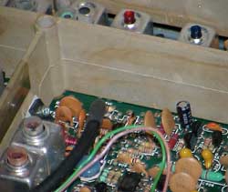
The wire I showed connected to the PL
board pin-5 is wired in with a diode and resistor (nicely heat shrinked
in red here) and pointed to by the yellow 'D'.
I normally put a diode in line so that I have options to have other devices paralleled in my system, and a 2.2k resistor in series for protection from 'oops'. The other yellow callouts are showing places where components were removed from the transmitter audio section for the 'flat audio' (a/k/a '9600 baud packet') modification that I put in on the transmitters.
|
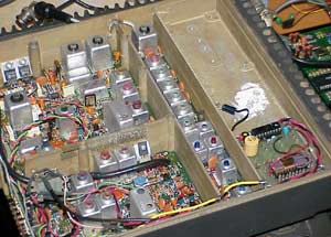 |
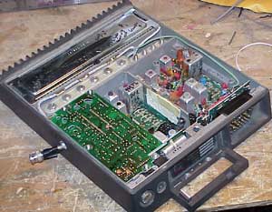
Switching gears, I've never liked how
the Mitreks heat up after a long ragchew-- even when they are throttled
down considerably in power.
When I have a choice, I prefer to use the Micor 100w continuous duty external PA units. These work fine with just a watt or so of drive and keep the heat out of the Mitreks. I've also found that the extra chassis space where the Mitrek PA was can be put to good use (multi-tone PL encoder in this view). |
 |
The first thing you need to do to
perform the 'exciter' modification is to drill a little hole for your
coax to escape from the transceiver.
Surely there are more elaborate ways to do this, but if you do it this way, and leave the PA board in the unit, it is possible to quickly restore the unit to full power should you need it later on. There's just enough room to run some RG58 (or better) coax next to the t/r relay. |