 |
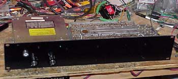
This is the 440MHz receiver used to receive the UHF signal from the W8TVC site and provide audio
and COS to the two voting systems.
Presently, the RF portion is an old Motorola
"H" series Motrac receiver. Once new crystals are in
hand, this will be upgraded to the better "M" series Motrac
receiver. The two knobs are for volume and squelch should it be desirable to plug a speaker into the unit for troubleshooting. LED's indicate which of the two PL/CTCSS decoders are triggered. |
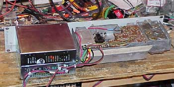 |
This view shows the rear of the unit. To the left of the receiver is the enclosure housing the two CTCSS decoders. I scavenged the casing from an old computer power supply for this use. The size worked out perfectly! |
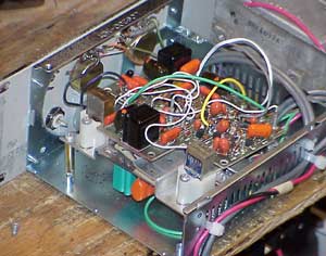 |
This view shows the two CTCSS
decoders. These were recycled from RCA 700 series
transceivers. With a little fiddling, I have one mounted to the chassis
where an encoder would normally be located. This arrangement does
the trick and saves me from spending another $120+ on brand new
decoders.
The SO239 connector on the front panel is there to fill a hole in the panel that was used in a previous life. I had wanted to put a headphone jack in that position, but the CTCSS decoders were in the way. |
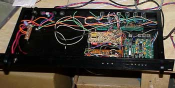 |
This is the controller chassis.
To the right in front is the NHRC-4 controller.
I mounted things to one side so that in the future there is room for expansion. If this portion of the repeater keeps up with the rest of it, there will be expansion in the future. At the moment, nothing is planned... but who knows! |
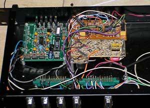 |
From the rear, the NHRC-4 is on the
left, with a perfboard containing custom circuitry in the upper
right. Below the perfboard on the right is the PL decoder from an
old Motorola MHT Motrac receiver. This PL decoder is part of the
circuitry which is used to link the 444.725/52.92 wI0OK repeater to
the 145.27 W8TVC repeater.
Just behind the 9pin-D connectors are two surplus 'card edge' connectors which are used here as terminal strips. I've run very low on terminal strips and they can be pricey compared to my excess supply of unused edge connectors. It's very easy to spend tons of money on this stuff. It seems as if at every turn there's another $70 going out the door for small, but necessary, items. The larger the project the more the necessary items! |
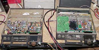 |
This photo shows the two Mitreks used
for the main portion of the voting system. On the left is a Mitrek
tuned to 52.42 which has the transmitter power amplifier removed (and
the mod to feed the 'exciter' output). This unit is one of the
pluggable spares for the main wI0OK six meter repeater rig. This
will be six meter receiver #2.
On the right is a Mitrek tuned to receive on 449.725 and transmit on 440.05. This will be the 449 receiver #3. The little black item in the middle is a PL tone encoder used to provide switch able PL tones on the 440.05 link so that the receiver system knows which receiver is active. |
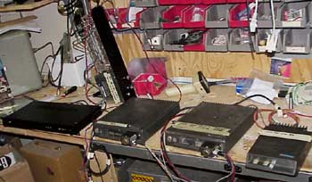 |
The whole setup is shown here with the
controller chassis on the left and the 440.05 link receiver behind it on
its side.
On the very right in the view is a Motorola Moxy 444.725 receiver which was originally planned to be part of the linking system but was swapped for an old RCA-700 UHF transceiver because the 10.7mhz IF in the Moxy receiver, when used with a crystal suitable for receiving 444.725MHz caused a strong local signal to appear on the 144.67 input to the W8TVC repeater. The old RCA transceiver being used was formerly (years ago) the 444.725 repeater itself and is saved from the landfill for this function. As an added bonus, the RCA is setup to transmit on 442.025MHz (at 60mw) the signal from the 444.725 repeater. This was done so that Dave, W8TVC, would be able to have solid HT coverage into the GlenArbor-Empire repeater from his home. The voting receiver gave him a solid signal into the repeater, this new 442MHz transmitter allows him to hear the repeater without worrying about where he places his HT. |
 |
In mid August the system was
finally put into service. The photo at the left shows the
equipment at the W8TVC site (the
green rack on the left is the W8TVC 145.27 repeater).
At the top of the rack, in the rack shelf, are the two Motorola Mitrek transceivers. The very top one is the 440.05 transmitter (link back to Glen Arbor) and the 449.725 receiver. The lower Mitrek is a receiver on 52.42. Below the Mitrek shelf is a black box containing the voting repeater controller. Since the operation of these remote ('satellite' is the official nomenclature) receivers resembles that of a repeater, this system needs to adhere to normal repeater rules. The controller provides control, timeout, ID (wI0OK/L), etc. Below the voting system controller is a backup controller for the W8TVC 145.27 repeater (an RC1000) and a backup GE Mastr2 repeater. At the bottom of the rack is a 12v power supply on the right. On the left is a receiver that receives the 444.725 repeater output (changed post-photo due to the LO of the IF getting into the 144.67 receiver in the adjacent rack). |
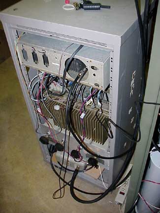 |
The back of the voting
receiver rack shows the typical maze of wires one finds in these more
complex systems.
Below the gold colored heat sink (for the GE Mastr2 rig) is a Motorola UHF duplexer that combines the 440.05 transmitter and the 444.725 receiver and feeds them to a five element yagi at 50' for the link back to Glen Arbor. At the very bottom of the rack is a single Motorola bandpass cavity tuned to pass 449.725 for the UHF voting receiver. Not shown here are ARR GasFET preamps for the 449.725 and 52.42 receivers, those will be installed after the voting adjustments are optimized. |
| Schematics of this portion of the
system will be on here soon.
Photos of the antennas will also be forthcoming. The 449.725 receiver is fed by a Diamond X50A mounted inverted at the 70' level on the north side of the tower and connected via 7/8" heliax (Thanks to N8JKV-- and his rescuing the cable from K8DT's trash, years ago). The 52.42 receiver is fed by a Cuscraft AR-6 ringo at the 70' level on the north side of the tower. This antenna is connected via some Andrew equivalent of RG8 (not sure of the precise number-- purports to have 9913 specs). The link back to Glen Arbor/Empire is via a Cushcraft 5 element 440 yagi at the 50' level on the tower and fed with some 7/8" hardline of unknown origin. |
Thanks to Keith WA8ZWJ, still action photos from the day the antenna work was done are available. |
| Return to the wI0OK/r Glen Arbor repeater page. | Repeater controller upgrade Repeater antenna upgrade |