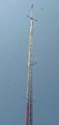
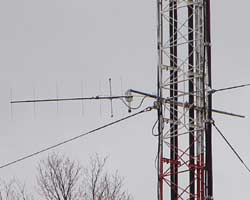
This is the view of the 400' tower that
primarily holds the antennas for the 95.5 and 98.1 'Real Rock' and 'The
Bear' FM stations (WJZJ, WGFN) licensed to Glen Arbor. The
site is south of Glen Lake and east of Empire and just north of M-72 atop
a good sized hill.
Also on the tower are two 'cellphone' companies, and a local gas company.
This photo was taken before the 'new' repeater
antenna was placed at the 330' level on the tower.
You can see the remote-base and secondary receiver
antennas in this photo, as they are at the 100' level. There is also
shown a 220mhz AEA Isopole at the 60' level, that has since been removed
and replaced with a 7 element 220mhz M2 yagi. |
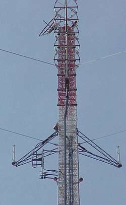
This photo shows our
antennas on the left, just above the side marker lights, and below the
sidearm for one of the cellphone antennas.
While it might have been nice to put the antenna at
the very top, this location is 'just ducky' as it's not going to be the
first thing a lightning strike will want to hit-- and it's at least a few
feet away from all that FM broadcast energy.
This image is looking west.
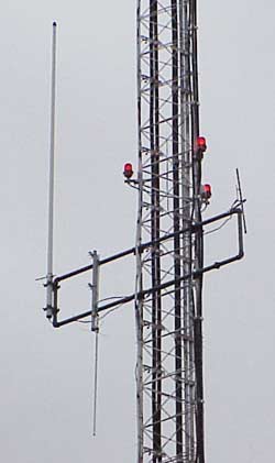
From this view you can only make out the single element DB products vhf-low (6m) folded dipole. Intermixed with the 6m antenna on the mastpipe is a DB products four bay UHF antenna for the 444mhz repeater.
That VHF-lo/6m antenna is also used by the 145.36 DStar repeater. While the SWR on 2m is far from ideal, the radiated and received signals using this antenna are far greater than my next best alternatives-- so the SWR is tolerated in exchange for better coverage (that makes good logical sense to anyone but an asshole-- you could call it an AH test of sorts). |
Below on the left you can see the 450 Mhz Cellwave
Super Stationmaster antenna at the outer end of the mount. This is
presently hooked up to 449.725 receiver #3 and also is used to receive the
Traverse City link signal, and is also connected to the UHF control
receiver. What is particularly good about this antenna, even
though it's only at 100' on the tower, is that it's orientation is
somewhat different giving it the ability to fill in for a bad UHF tower
shadow in nearby downtown Glen Arbor. HT coverage at the local
watering holes is still possible.
On the left, just inside the UHF Super
Stationmaster, is a dualband Diamond X50A modified for
inverted mounting and connected to the 2meter and UHF packet systems.
On the right side of the mount is an element from a
2mtr dipole array. This is a vestige from a former packet node and is mostly used for feeding RF through the system
from my signal generator when I am tweaking things.
Below
on the right you can see another six meter DB products folded dipole, also at
the 100' level. This antenna sometimes feeds a third 52.42
receiver. Temporarily this 6mtr antenna is being
used by the 2mtr remote base transceiver via a diplexer. Next time up the tower it should be swapped out for a 2mtr antenna. |
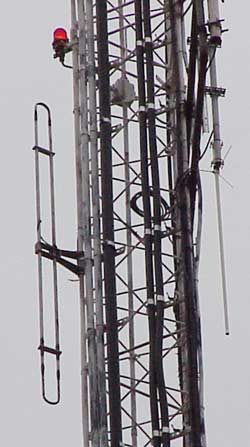 |
To the left is the M2 Antennas 7 element 220 yagi
aimed at the WB8DEL repeater in Stutsmanville. This is at
approximately the 60' level on the tower. |
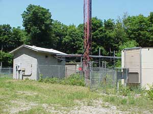
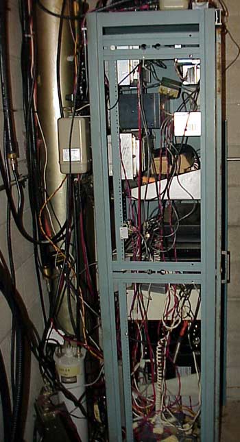
These photos show the tower base and the
concrete block building that houses the radio equipment. The
cellular phone operators have their own 'prefab' buildings to house their
equipment.
|
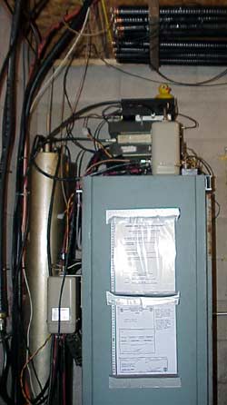
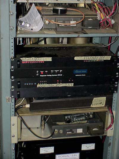
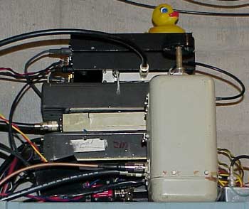
The wI0OK repeater rack sits quietly in the corner of the
building and is watched over by the careful eye of a guard
ducky-- our
local control operator.
This rack has removable side panels and doors and was previously used
for the 147.30 repeater, many years ago. Sadly, the doors spent some time outside
and need to be repainted. The little handles on the front of the DStar gear prevents the front door (now removed) from closing. Sometime I'll have the ambition to remove the DStar handles, but for now it's working fine.
Regretfully, the rack is just so big and some of the
gear is finding itself relegated to the top of the rack. Behind the rack are presently two six meter bandpass cavities which add some extra isolation from the strong nearby broadcast transmitters (the heliax duplexer is notch-only!).
Bolted
to the rear is yet another 440 bandpass cavity for the primary 449.725
receiver. Another bandpass cavity atop the rack is for one of the
other UHF receivers.
Atop the rack is a stack
of radios which comprise the packet system. Mounted
above the rack, to the roof trusses, is the heliax six meter duplexer. Overhead as this photo was taken is where the DStar duplexers are positioned. |
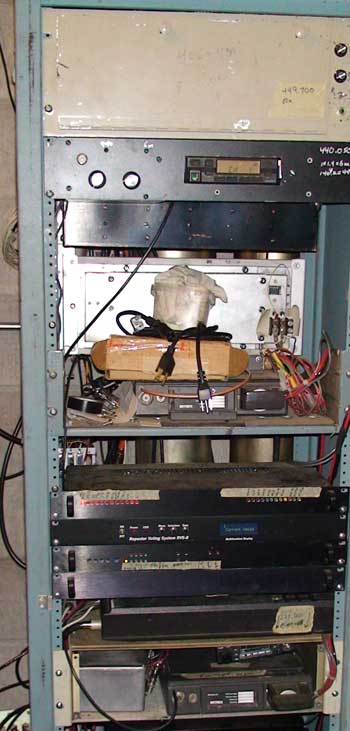
This photo shows the overall view of the
front upper portion of the repeater rack before the DStar gear was added.
Thankfully, the rack has both front and back 'rack
rails' so equipment can be mounted on either side of the rack.
At the top of the rack is an old Motorola 'M' series Motrac
base receiver which is used for the 'FCC-legal'
control system.
Behind this receiver is a Micor 100w power amplifier
for the 52.92 repeater.
Visible below the Motrac receiver is a panel where a Kenwood TK860 is mounted. This receiver is used to pick up the signal from the W8TVC repeater site that carries both 449.725 and 52.42 remote receiver signals along with signals from the 145.27 repeater.
The black box just below on the rear rails is a Cellwave six cavity UHF duplexer for the 444.725 machine.
At the middle of this view, on the rear rack rails
is a Motorola Micor 75w base UHF power amplifier for the 444.725mhz transmitter.
Below the brown cardboard box containing 'spare
parts' is the main unit of the 444.725 Motorola Mitrek used as the UHF repeater.
That empty space below the Mitrek shelf is now filled (see below). Below that are four rack boxes that comprise the repeater control system. |
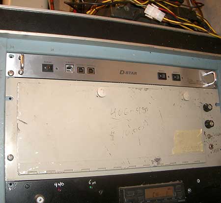
This is the view of the top of the rack showing the DStar RP2C controller in place above the UHF control link receiver. This unit has since been moved to the Traverse City tower along M72.
While it would have been nice and pretty to mount the DStar components all together in the rack, there were issues with other items mounted to the rear rack rails that preculded that.
Yes, both the front and rear rails are used in this setup-- and it can be an interesting juggling act to change things. Thankfully, with the side panels removed, it's possible to get to the rear panel connectors without having to remove things. |
In this mid rack photo, you see the Motorola Mitrek
444.725MHz and 449.725MHz main repeater transmitter and receiver sitting
on a rack shelf at the top.
This Mitrek has been modified for 'exciter output' as you can see the
RG400 coax coming out just above the normal antenna connection. This
feeds the Micor PA quite nicely and keeps the Mitrek from heating up
during long QSO's. Out of view is the Advanced Receiver Research GasFET
preamplifier.
Below the shelf with the Mitrek is four black rack mount boxes which comprise the
repeater control system. Those boxes are stuffed full of all
sorts of electronics and provide a great many 'bells and whistles'. The
top box holds the Arcom RC210, the second is the LDG RVS-8 voting
comparator used for the 52.92 repeater. The third contains the Doug
Hall Electronics voting comparator used for the 444.725 repeater, along
with some ancillary controls. Finally, the fourth black box contains the
seperate 'FCC Legal' control system.
Under all
the black boxes is a Motorola SyntorX formerly used for the synthesized 2mtr remote
base. Sadly, after years of great service the SyntorX developed a temperature dependent squelch problem and was replaced by a Kenwood TM-271. I just plain did not have the time to devote to recreating the intermittant problem (which conveniently occurs only while I am wintering in Arizona!). That SyntorX has been repurposed and rides along in my old green van as my APRS node kf8kk-9. |
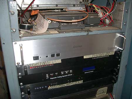
This updated photo shows the DStar RP2000V 2mtr RF deck squeezed in below the 444.725mHz Mitrek and above the Arcom RC210 controller.
Moving the DStar repeater out of this rack gave me back some working room for tweaking the controller! yee haa!
|
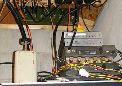
Below the SyntorX is a rack shelf with the
weather receiver in a grey box on the left. This
little weather receiver also has the ability to decode the S.A.M.E.
weather alerts and feed them onto the controller to signal that
threatening weather is approaching.
To the right of the weather receiver is a Motorola Mitrek
that comprises
the 52.92MHz transmitter and 52.42MHz receiver. This Mitrek
has had it's PA section removed and it feeds it's Micor 100w power
amplifier directly (PA at top of rack in rear).
Atop the 6mtr Mitrek is an Icom IC37A 220MHz
transceiver which is the 220 link rig. This transceiver is set
to 10w output power, which provides plenty of signal to access the WB8DEL
Stutsmanville repeater. The IC37 sits at an odd angle for
better cooling, at the expense of cosmetics.
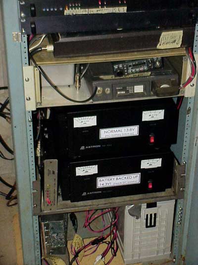
The two Astron RM70 power supplies provide the 12v
for the system. The top supply powers the devices NOT on the backup
battery, while the lower supply feeds a power isolator and all the items
receiving emergency power.
To the left of the lower Astron is an MFJ1270 TNC
formerly used for the wI0OK-8 'BENQMN' TheNet X1J packet node on 145.76.
At the very bottom, on the left is the home built
power isolator. On the right is a 500 amphour deep cycle battery
used to supply the repeater with emergency power. |
The complete 444.725 repeater, 220
remote base and packet gear is equipped with emergency power and should have enough
'juice' to go for a few days (perhaps a week) without
problem. The six meter side and DStar will go 'dark' without commercial power.
This photo shows the side of the rack with the
52.92MHz Motorola Micor 100w power amplifier at the very top on the rear
(left) side.
Below the six meter amp is the six cavity UHF
duplexer and below that is the 444.725MHz 75w Micor power amp.
There is a pair of 'muffin fans' which keep the air
circulating over the UHF Mitrek and the power amps.
As you can see, there are many wires connecting the
various items.
On the lower left is a bandpass cavity for the
145.07 packet node.
Next to the bandpass cavity is yet another 52.42
receiver for the six meter repeater, this one (from an RCA700 system) is connected to the lower
6mtr antenna (though it is unused at the moment). |
Atop the rack is where I used to have a three port X1J4 TheNet packet node. This has since been taken out of service. I've put online a few notes on how I convert Motorola Mitrek's for repeater
use, along with how I built that battery
combiner
Starting
at the bottom, there is a Motorola SyntorX transceiver which was the
wI0OK-7 145.07 TheNet node. This has the 'hi sens' option and is tuned
back to 60w. The TNC connected to this transceiver is the very top TNC,
the MFJ1270 just below the Control Operator Ducky.
Above
the SyntorX is a UHF Motorola Mitrek ('rx-2') which is used as the #2 449.725
receiver, and could be placed into service as a backup for the main
444.725 repeater should the other Mitrek fail. This receiver is crucial for HT coverage at Arts Tavern in downtown Glen Arbor-- it's fed with that lower antenna that does not have a nasty tower shadow to the downtown area as the higher antenna has. |
Atop
the 449.725 'rx-2' Mitrek is a six cavity mobile duplexer. This is used to feed
RF to both the alternate 449.725 receiver and the 440.05 link receiver and
provide adequate isolation from the other UHF transmitters on site.
Atop
the mobile duplexer duplexer is yet another Motorola Mitrek. This
Mitrek was the 433.125/438.125MHz bit regenerative 1200 baud packet
repeater. This is the wI0OK-2 TheNet port. Atop this Mitrek are the TNCs associated with this packet node, two MFJ1270's.
Behind the rack, atop the block wall is a lime green six cavity Celwave UHF duplexer which was used for the 433mHz packet repeater (and is now part of the 442.2 Harrietta rptr)-- even atop the rack I ran out of space!
I have a special
packet page with information on the local packet systems and how to
get the most out of TheNet and Jnos from a users perspective. |
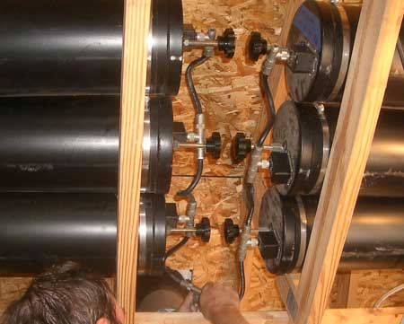
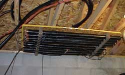
Above the racks, in the roof truss system is where I've managed to place the two meter and six meter duplexers.
Shown here is a really swell 2m six cavity duplexer that is used for the 145.36 DStar repeater.
|
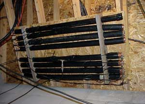
If you stand in front of the repeater
rack and look up you can see the eight stub heliax six meter duplexer.
This was the first of these that I've built using
the WB5WPA
design.
This duplexer works great and has been trouble free.
Thanks to Del WB8DEL for donating the heliax (amongst other things).
The duplexer fits nicely on a 4' x 2' piece of OSB
and mounted to the bottom chord of the roof trusses. It was tough to
get it up there, but it's out of the way. |
I plan to build another of these
duplexers, with more 'beefy' interconnecting cables, and then crank the
power on 52.92MHz up to the full 100w the system is capable of. I
hesitate running the system at full power as I used RG58 in the interconnecting
cables and wish for more 'reserve' power handling capacity.
I have a page with more info on building one of
these 6mtr duplexers. |