Six Meter Heliax Duplexer Construction


KF8KK.COM

Repeaters

Coverage Maps

IOOK.ORG

Thanks to the excellent work of WB5WPA, it is possible to create a useable duplexer capable of handling a high power 500khz split six meter repeater.

At the time of this writing, I have built three such duplexers and they do indeed work 'as advertised'.   Construction isn't terribly hard, and neither is tuning.  From my description you will see that the original design can be modified somewhat and still function, and you can still tune the stubs even if you don't have all the latest test equipment.  While I did have a good (though quite old) signal generator, the only other tools required to tune these is a soldering iron, pliers, some sort of tunable receiver or scanner, and patience.

The first two sets of stub duplexers I built used the foam version of the 1 5/8" hardline that WB5WPA used in his design.   When I went to build the third set for a friend I discovered that I had run short of the foam hardline but had plenty of air-dielectric available.   With slight tweaking of the heliax stub lengths due to the different velocity factor for the air heliax, there was no problem making the air-dielectric hardline work just as well as the foam version.   Either seems to work the same, just make sure you tweak the length for the velocity factor of the hardline you are using.

This is a look at the first heliax duplexer that I built.  It is currently in use on my 50w 52.92 repeater, wI0OK in Glen Arbor, MI.

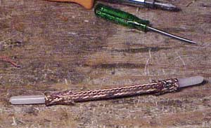
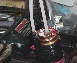
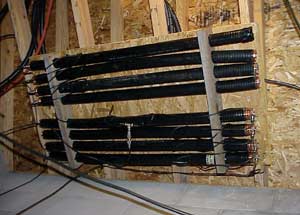
While it's nothing pretty to look at, it does it's job.  I can spend the money that would have gone into a duplexer on other, more necessary, things.

The first thing you need to do is to procure the heliax.  The first two duplexers I built used the foam dielectric version, but the third set (pictured here) uses the air dielectric.  You just need to adjust the overall cavity length when using the air dielectric.

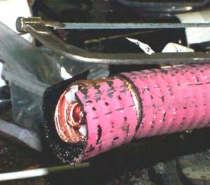
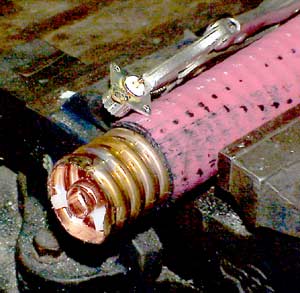
Once you cut your stubs to length (keep those for TX seperate from RX) you need to strip off a few inches of insulation from both ends.   While a sawsall with a metal blade is the quickest way to cut the heliax to length, stripping the insulation is best done carefully by hand with a hacksaw and a drywall knife.

The 'bottom' of the stubs needs to be an electrical short.

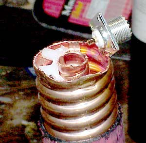
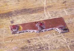
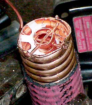
There are numerous ways to do this, I chose to take some #14 copper wire stripped out from some excess romex (household electrical wire) that was left over from a recent home addition.

If I was using the foam core heliax I would use my drywall knife and then a screwdriver to cut (and pry) out some of the foam so that I could run my shorting wires.  The air direlectric heliax saves me that step (and it's a nice step to save-- cutting that foam isn't as easy as it sounds).  

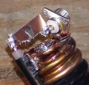
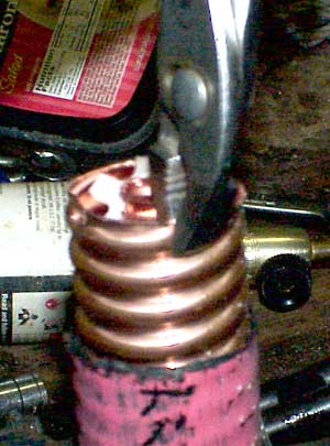
Once the area is clear of foam I then use a pair of pliers to flatten the outer conductor so that when I drill the holes for my wire the drill bit doesn't want to dance all over the place.

This shot shows the two lengths of #14 copper wire threaded through the end of the stub.

As I said, there are many ways you can 'electrically' achieve the same result.

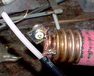
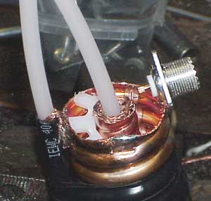
It helps if you clean off the copper with emory cloth or some scotchbright.  Soldering to this takes a LARGE (300w) sized soldering gun or a torch.

While most of the stubs were soldered using the typical rosin core solder that is normally used in electronics work, I have also been successful in using paste flux and 'plumbers solder'.  Being that the pieces being soldered are more remniscent of plumbing, the job seemed to go quicker when using the techniques one would use to sweating pipes.  The end result was about the same.  Prepare to use plenty of solder!

This photo now shows the 'top' portion of the stub.  As with the bottom, you need to clean out the foam dielectric a little so that you can work.

I've tinned with solder a corner of the 'silver plated' SO239.  I've done this with BNC's too.  don't cheap-out on the connectors-- get the good ones.

After cleaning the copper end of the heliax I tin the spot with a generous amount of solder where the SO239 is to go and then I hold the connector where I want and heat that spot with a torch until the solder flows.

In this shot you can see the SO239 mounted onto the end of the stub.

You not only want a good electrical connection here, but a good mechanical hold also.  Any movement in the connector will tweak the frequency of your notch.

While at this stage, you will want to tin a spot on the opposite side of the end for connection of the shield from the coax jumper, and then another spot about 90 degrees around the edge from the SO239 for the later connection of the small variable capacitor or coil.


This shot shows how the length of RG213 'interconnection jumper' is connected.   

It's cheap, quick, and simple.  Just make sure not to melt the insulation of the cable.  It takes a bit of a knack to get the shield onto the heliax and get the solder to flow and then move the torch away so it solidifies nicely-- all without applying too much heat or moving it as it sets.

Since the length of the jumper is critical (not overly so, but you do want them to be a certain length) you might want to make a few 'dry runs' with scraps to get the hang of this.

The original plans call for another connector on this end, which is fine-- but I'm a cheap bastard and this works for me.

This is the gimmick capacitor that goes on the inside of the heliax center conductor.

After you fold back the ends (as shown) of the RG213 shield, you may want to provide just a little bit of solder tinning to keep the thing from unraveling while it's being worked on.

Before you go further, make sure the ends of that RG213 center conductor are rounded so that when it is removed or inserted into the gimmick later on it does not snag on the braid and distort it.

This photo shows the gimmick capacitor in position on the top end of the stub. You want the top of the gimmick to be roughly flush with the top of the heliax center conductor.

Remove the piece of the gimmick that was the center conductor of the RG213 (carefully!) and then solder around the top of the gimmick braid so that it is electrically and mechanically affixed to the heliax center conductor.

Sometimes when you pull or push on the gimmick it will want to follow that piece of the RG213 in or out.  Be gentle and patient, you don't want to cause an irregularity in the braid... It's much easier to tune the stub if the center piece slides smoothly and without distorting the gimmick braid.

In this photo you can see that the gimmick braid is soldered to the center conductor of the heliax.

I have also taken some electrical tape and taped the RG213 to the outer shield of the heliax.  This is done to provide some rigidity and strain relief.   Just as we need the SO239 to be mechanically stable, the RG213 needs to be stable also.

Here is a piece of scrap single sided PC board material that I used as the jumper between the center conductor of the SO230 and the center conductor of the RG213.

I happened to have some old PC boards on hand, there is no other reason than that for this choice of material.  I cut it to shape with a nibbling tool and then tinned it where it would be connected.

This photo shows the jumper connected.  It is important to have a mechanically sound connection just as an electrically sound one.   You also need to try to line up the jumper so that when the center piece of the gimmick capacitor is in place that the wire of that lays gently on the jumper for easy alignment and soldering.
In this photo it's pretty much done.

I have slid the gimmick capacitor center lead into the gimmick braid and have enough of that center lead stripped clear so I can move it up and down for tuning.

Tuning these isn't a black art, or requiring knowledge of rocket science.   It does take PATIENCE and COMMON SENSE.   You don't need the real expensive tools, but a stable signal generator with a good variable attenuator is a must.

Set your receiver and signal generator on the frequency you wish to notch and set the generator for about 10db more signal than it takes to open the squelch on your receiver.

Squeeze the center wire of the gimmick capacitor against the connecting jumper with one hand and slide the gimmick wire up and down with your other hand.

If you're lucky, you should find a notch pass through your desired notch frequency when you do this.

If you're not so lucky, you may want to change the length of the center wire in the gimmick.  These things DO work-- but I have seen some where for one reason or another the length of the gimmick wire inside the gimmick braid was a bit off of where I had expected.

If you don't get a notch on your frequency, try going up or down the band 100khz at a time and see if you can locate where the notch is, and then contemplate whether you need more or less of a gimmick wire.

Once you get the gimmick close to where you want you can then solder the small variable capacitor or coil between the jumper and ground to provide the little 'bandpass bump' in the response.   This is not shown here.   The little coil or cap shouldn't effect the frequency of the notch at all.  I usually install them just before final final final tuning as I consider final tuning to be final.

I have found that for final tuning, an small set of needle nose pliers with insulated handles gripped onto the gimmick doesn't affect the frequency much and you can heat the jumper to flow the solder and move the gimmick to the right spot and let the solder solidify and be right on frequency.  You will want to check to see if you are centered on your desired frequency by checking to see how much signal 'breaks squelch' at 10, 20, 30khz above and below the desired frequency.  

I've seen immeasurable attenuation on the desired pass frequency (though my measuring capability is severely limited and laughable by scientific standards-- considering, however, what this is and what it's doing, my measuring capability is just fine) and roughly 17 or more DB of loss per stub on the desired notch frequency, often near 19db.

After the stubs are tuned they should be mounted in a manner that will keep them secure and the 'top' ends protected from movement.

One of the drawbacks of using the air dielectric heliax is that the stubs are a little longer than their foam counterparts and therefore need more than a 4' long piece of plywood or OSB for mounting.  A 2" hole saw does a fine job of poking holes in a 2x4 for passing the heliax.  Some long ty-wraps help hold things securely in place.  I have also added some 'Great Stuf' spray foam for additional stability.

The set of duplexers shown here was built for KG8CU and his 52.82 repeater.  The repeater is presently using these and they reportedly work great!  As you can see by the coloring, the hardline was not brand new.  Outside of the used 1-5/8" heliax the cost of materials was about $30, and roughly a days effort.

I have been building 8 stub duplexers as I felt the added isolation of the extra stubs (one on each side) was desirable.  It's not all that much more work to make two more stubs when you are already making six. It would have been a royal pain to make the extra two stubs later on, after all the tools were put away.  With the extra two stubs, should some drifting of the tuning take place, I would likely not notice any change to the repeater operation until it got severe.

Final Observations:

Just to let you know, building these is NOT my favorite pastime. 

While it's not a hard thing to do,  I promised myself to just build one more set-- the set for my higher powered wI0OK 52.92 repeater.  There are VERY VERY few friends who I might entertain building these for-- and chances are near 100% I would have to respectfully decline building a set for YOU.

The first two duplexers I constructed used fairly cheap RG58 interconnection cables.   While this made the interconnecting cable lay very neatly next to the stubs, I like the idea of the larger, RG213 cable as it can handle higher power levels.  Pretty much any 50 or 52 ohm coax can be used for the interconnections, you just have to take into account the velocity factor when figuring the lengths.

As far as the lengths are concerned, I tried my best to be as accurate as possible and adhere to the recommendations of WB5WPA.  However, because I changed the design by using just one female connector at the tuning end of the stubs, my interconnecting lengths may be off somewhat.  Ultimately the duplexers still work fine.  Because of this, I suggest that the exact lengths of the interconnecting cables are not super critical-- an inch +/- is likely to be fine.   When I made the interconnecting cables I cut them long and then put the connector on one end and then cut the length after the connector was in place.  This saved tons of grief if the connector wasn't cooperative in mating to the cable.

Remember that these are NOTCH ONLY stubs.  There is almost no bandpass characteristics to them.  If you have a strong local 'out of band' signal that you need to reduce you would have to determine the frequency of that and build a stub to drop that signal down.   This duplexer passes everything but your desired notch frequency pretty well.

As you can tell by what is displayed on this website, I'm not a 'technical purist'.  Yes, I do strive for the optimum performance (and usually achieve it) but I don't pretend to create 'mil spec' systems nor do I wish to forego other niceties of life just so my ham stuff looks 'pretty'.  This is a HOBBY for me, and I intend to ENJOY it (part of the definition of hobby).  I get great enjoyment out of taking items that others consider worthless garbage and making them do amazing things.  It's tons of fun, and it leaves the money others would have spent on expensive ham gear available for more important 'quality of life' items.

If you find this project of interest and have a question feel free to email me at

73  John  KF8KK