 |
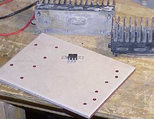
I found a nice Schottky diode pair in
the DigiKey catalog and bought a couple of these fine devices. The
diode is shown here atop a scrap piece of ceramic floor tile.
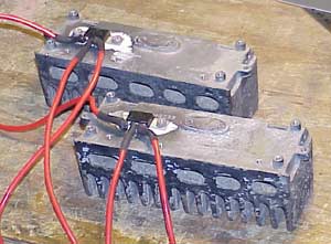
Being that there's a fair amount of current flowing through the diode during normal use, it needs a good heat sink. When I trashed a pair of old Motorola Mocom-10 transceivers I kept their power amp heat sinks 'just-in-case'. Those heat sinks are shown here and, it appears, are a bit of overkill. |
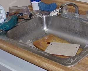 |
One of the things that's nice about
having built my own house is that I've got the tools handy for lots of
odd things... the drill bit to put holes in ceramic tiles being one of
them. Make sure you run water over it to keep it cool!
As it turns out, the 'common' lead (the part going to the load) of the diodes is also connected to the mounting tabs. This means that I will either have to insulate the heat sink electrically from the diode mounting tabs, or isolate the entire heat sink from the rest of the world. Since I didn't get the special little insulating pieces, I have no choice but to electrically insulate the heat sinks from ground-- and a couple of scrap ceramic tiles will do the trick nicely. |
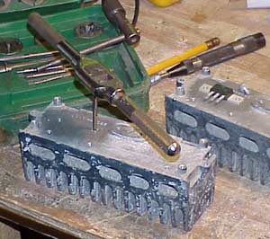 |
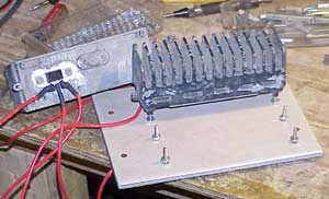
After cleaning the spot on the heat
sinks for my diodes I drilled and tapped the appropriate holes.
Of course, some white colored thermal transfer compound makes sure that the heat is dissipated in the large aluminum blocks. I am actually building two isolators in this project. One isolator feeds the repeater power amplifier, and the other feeds the rest of the system. |
 |
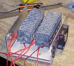
The diodes I'm using are International
Rectifier 112CNQ030A and are capable of 55 amps per side (110 amps total
per device). I wanted to have a generous margin of comfort,
so I split my load (which would have a maximum of about 25 amps) between
two devices.
This view shows the diodes mounted to the heat sinks with the wires for 12v hanging off them. |
 |
If I had plenty of time to wait for
spacers from the supply houses I could have mounted these to the tiles
in a more fashionable manner. Since I didn't feel that it
was something critical, some long 6-32 screws and an appropriate supply
of matching nuts was used to mount the heat sink assemblies off the
ceramic tile in such a way that the diodes are not pressing against
anything.
|
 |
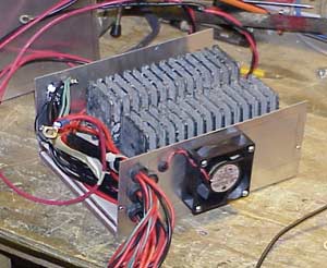
The isolator is now taking shape and you can see the 'Bud Box' with the two ceramic tile insulators (the second one isolates the heads of the 6-32 screws from the box). A nice little fan is on the right to make sure plenty of air passes over the heat sinks. I didn't want to take any chances. |
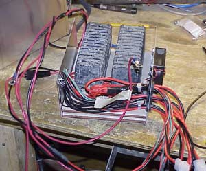 |
There is not a whole lot to one of these isolators. Just a bunch of wires and plugs. |