 |
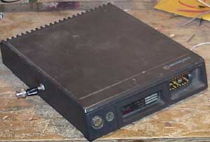
This is a Mitrek modified for the
external input for the receiver.
The receiver connects to the BNC connector coming out through a hole in the side. The transmit signal still comes out the UHF connector on the front of the unit. This is a 30-50w Mitrek which can be easily seen by the shorter length of the unit. The 75-100 watt units are a bit longer and the heat sink fins are longer. |
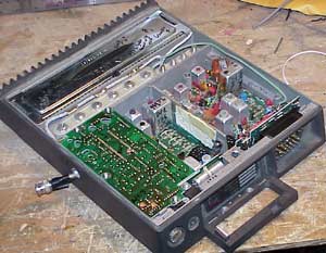 |
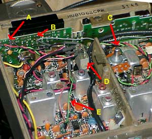
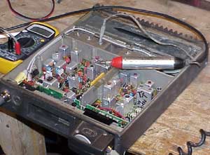
The inside of the Mitrek shown above
has the PL decoder board on the left (mounted from the top).
Between the shiny chrome PA cover and the PL board is the helical resonator section. The six resonators on the left are for the receiver, while the four on the right are a filter for the transmitter. You can tell which band Mitrek you have by taking a quick look at the helical resonator section. This Mitrek is a UHF model (good for 440mHz ham use).
|
There are two 'band splits' of VHF-Low Mitrek. One covers the 42-50mhz segment and can be easily converted to the six meter ham band (it'll tune there without any changes, but there's a few capacitors to change for optimum receive). The 30-40mhz split Mitrek can be converted for use on the 10 meter ham band. Be careful to get the band-split that you desire. |
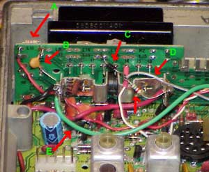
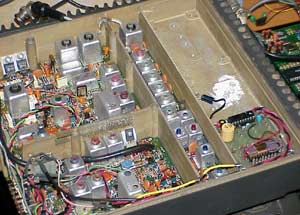
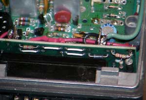
This Photo shows a VHF-Low Mitrek.
In the space where the helical resonators are on a UHF model, the Low-VHF units have typical coils inside shields. The top seven coils in this unit are part of the receiver 'front end'. The lower four (with the bright blue and red tops) are part of the 'extender' option. On VHF-Low you will find that man made noise is a big problem. The 'extender' is Motorola's name for a noise blanker. The Mitrek noise blanker ('extender') is excellent and renowned. If you're running a rig like an FT100D or IC706 you will notice quite an improvement on switching to a Mitrek with the extender. The extender is an option-- and on many (mostly the lower powered versions) VHF-Low Mitreks you will find that this section of the transceiver has a circuit board without the parts mounted on it. This particular unit has had the power amplifier removed and a PL encoder put in the space. I have modified this to feed the 1w output of the 'exciter' to a Micor external power amplifier.
|
 |
Here is a VHF-Hi Mitrek.
The helical resonator section is quite different and has a rectangular hole in the middle where an optional preamp can be inserted. Also in this view is an old Heathkit RF probe. You can see the DVM the probe is plugged into on the left. This is an inexpensive and invaluable tool when it comes to bringing the transmitters of some of these down to the ham bands from where they were in the commercial service. Of course, a spectrum analyzer is preferred, but there's a big difference in the price-- and this is quite adequate for the hobbyist. |
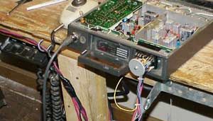 |
This photo shows the Mitrek on the
bench with a special cable connected which I have made that allows me to
easily get to the connector pins to verify that my connections
internally to the Mitrek are working. If you
plan to convert a few of these it's worth the time to get a test cable
made up.
You can also see the Mitrek control head on the left under the bench. I've also got a full Mitrek cable set which I use to verify that the units function BEFORE I start the modifications. It's incredibly important to check to see if the radio worked before tearing into it. Failing to test the radio first can cause you hours of anguish later on if it's not functioning. Thankfully, the Mitrek control cable connects via a connector that's the same used with old Motrac and Mocom70 transceivers and is relatively common and cheap (used). |
| The first modification I perform is to
take the receiver RF line from the T/R relay and cut it at the
relay. Make sure you cut the cable to the receiver.
I then drill a hole on the left side of the Mitrek and pass the receiver RF input through the hole and put a BNC connector on it. Photos of this will be forthcoming.
|
|
 |
The second modification I perform is to
jumper pin-1 and pin-25 on the connector that connects the 'interface
board' at the bottom front of the unit.
This jumper provides for the 'normal' operation of the PTT line. Normal meaning that the PTT is brought to ground when you want the transmitter to transmit. Ground pin-13 on the connector and it transmits. |
| In order to operate full duplex
(receiving while transmitting) you need to remove diode CR1 on the
transmitter and CR403 on the receiver.
Photos of these will be forthcoming.
|
|
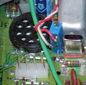
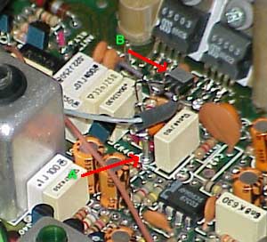
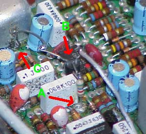
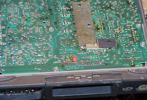
The photo above shows the jumpers which allow you to isolate the pins on the main connector from the internal circuits of the Mitrek. These are handy for changing the intended use of the connectors pins.
|
This view shows the main connector on
the upper left (the black piece).
On the 'interface board' (the vertical board that the main connector is soldered to) there are jumpers for each of the pins. Jumper 'L-9' connects in series with pin 9 on the connector. Removing these jumpers allows you to reassign the connector pins without worrying about what was connected to the connector previously. Jumper J-11 ('A') is where the discriminator output is found. This is where I usually take my received audio from (pin 11). If I need to have the received audio muted (when no signal is present) before it leaves the Mitrek I wire in a small relay across where J-11 used to be. 'D' in this photo shows such a relay. 'C' is a squelch pot wired in on this Mitrek. One side of the squelch pot gets connected to J-11 ('A') and the other side to ground. The center pin of the squelch pot goes to pin14 (or J-14). If you were to get your received audio from the pin-11 discriminator output there is no need to wire in a volume pot. FYI-- while the Mitrek schematic calls for 25k pots, I've used everything from 10k to 100k pots with fine results. I think Motorola chose 25k because they got a good price on a huge quantity of them. Unless you are a purist (stop reading and go away if you are) there's no reason to sweat a 25k pot. |